1996 58l Edelbrock Upper Intake Review Efi Intake Manifold
Best Sellers
How to Install an Edelbrock Performer EFI Intake Manifold on Your 1986-1995 5.0L Mustang
Installation Time
4 hours
Shop Parts in this Guide
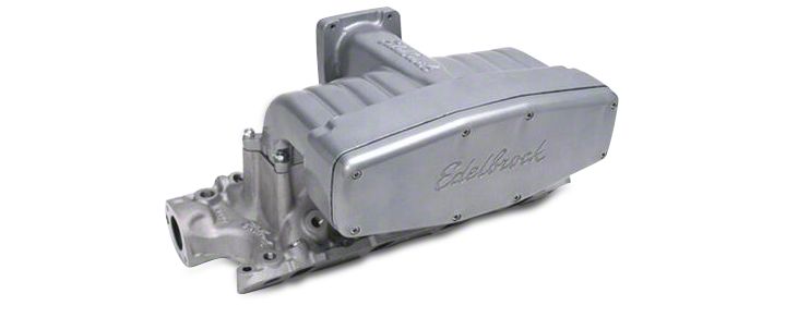
- Edelbrock Performer EFI Intake Manifold (86-95 5.0L Mustang)
Installation
Please study these instructions carefully earlier start this installation. Most installations tin can be achieved with common tools and procedures. Nevertheless, you should be familiar with and comfy working on your vehicle. If you do not experience comfortable performing this installation, it is recommended to have the installation completed by a qualified mechanic. If you lot have any questions, delight call our Technical Hotline at: ane-800-416-8628, 7:00 am - 5:00 pm, Pacific Standard Time, Monday through Friday or e-mail us at [email protected]
Important NOTE: Proper installation is the responsibility of the installer. Improper installation will void your warranty and may effect in poor performance and engine or vehicle damage.
Clarification: The Performer 5.0 intake manifold is designed for 1986-1995 5.0L Mustangs and passenger vehicles (will not fit trucks). It is ideally suited to street/strip applications with an RPM range of idle-5500 RPM. The manifold features a removable plenum cover allowing access to runners for modification if desired (not necessary for performance below 6000 rpm), and CNC port matched upper and lower manifolds for maximum period efficiency. Manifold Volition NOT clear mill 1994-1995 Mustang strut tower brace. Use Edelbrock Strut Tower Brace #5225.
KIT CONTENTS:
- 1 Base-manifold
- 1 Upper manifold
- one Plenum cover
- 1 Base-to-upper gasket
- 1 Plenum cover gasket
- 1 PCV valve bamboozle plate
- 2 #12 drive screws
- viii i/iv"-twenty x one" Allen head bolts
- 2 5/sixteen"-18 ten ane-1/2" hex caput commodities
- 1 5/xvi" x 1-3/8" carb stud
- 4 5/16" x 1-1/2" carb stud
- 5 5/16"-24 hex nuts
- 6 five/sixteen" split lockwashers
- 2 1/eight pipage to 3/8" hose fittings
- two 1/viii pipe plugs
- 2 3/viii pipe plugs
Emissions Systems: This manifold is intended equally a straight replacement for the factory intake manifold. All emissions related factory components are to be retained and functional. The manifold is, therefore, legal for street employ in all 50 states, and no C.A.R.B. E.O. number is required. Cheque local laws for requirements.
ACCESSORIES & INSTALLATION ITEMS: Major recommendations are listed below. See our catalog for details. To social club a catalog, telephone call (800) FUN-TEAM, or visit world wide web.edelbrock.com.
THROTTLE BODY RECOMMENDATIONS:
| Awarding | THROTTLE BODY | PARTS REQUIRED FOR INSTALLATION |
|---|---|---|
| 1986-1993 | 3824 (65mm) | 65mm EGR Plate #3827 |
| 3825 (70mm) | 70mm EGR Plate #3828 | |
| 3826 (75mm) | 75mm EGR Plate #3829 | |
| 1994-1995 | 3844 (65mm) | Throttle Trunk Adapter #3835 and Mustang EGR Supply Spacer #8025 |
| 3845 (70mm) | Throttle Body Adapter #3835 and Mustang EGR Supply Spacer #8025 | |
| 3846 (75mm) | Throttle Torso Adapter #3835 and Mustang EGR Supply Spacer #8025 |
NOTES:A 65mm throttle torso is recommended for utilise with the Performer 5.0 intake manifold on otherwise stock engines, while a 70mm throttle body is recommended for most street/strip applications as a part of our Performer Ability Package. 75mm throttle bodies should be used in college horsepower applications (Port matching required). The air valve (throttle body) location is 0.l" forward and 0.30" higher than the stock location.
If parts required for installation are unavailable locally, contact Edelbrock directly.
CAMSHAFT AND HEADERS: Performer Series manifolds are uniform with aftermarket camshafts and headers designed to work in the idle-5500 RPM range. Edelbrock has developed a dyno-matched, street-proven camshaft, Performer-Plus #3722 (For Mass-Air engines only), Tubular Exhaust Systems #6845, and Cat-Back exhaust arrangement #5645 or #5646, which are suitable for use with the Performer 5.0 intake manifold on 1986 through 1993 Mustangs. Consult your dealer, Edelbrock catalog, or Edelbrock Technical Hotline for applications.
CYLINDER HEADS: Manifold should exist used with modified or loftier performance cylinder heads to accomplish full power potential. Edelbrock Performer 5.0L cylinder heads are fully assembled, ready to run cylinder heads that are designed to piece of work with this intake manifold.
GASKETS: Do non use competition style intake gaskets for this street manifold. Due to material deterioration over time, internal leakage of vacuum, oil, and coolant may occur. Replacement plenum comprehend and manifold top to manifold bottom gaskets bachelor as Edelbrock #3832. OEM Ford gaskets will not fit.
| INTAKE MANIFOLD | REFERENCE | RECOMMENDED GASKET |
|---|---|---|
| 3821 | (None) | Edelbrock #7220 Port: 1.20" x ii.00", .060" Thickness |
Note: To ensure maximum performance and a proper seal, Edelbrock gaskets which are specifically designed and manufactured for apply with Edelbrock parts must exist used.
PREP AND TUNING FOR Ability:
Note: Local emission laws must be checked for legality of any tuning or ignition changes.
1. Aftermarket ignition kits may be used with Performer serial manifolds.
two. Apply modified or loftier functioning cylinder heads such equally our Performer v.0.
3. Installation of non-recommended aftermarket headers, camshafts or both with an Edelbrock Performer series manifold may require additional tuning.
INSTALLATION PROCEDURE
Earlier Beginning: This installation can exist accomplished using common tools and procedures. However, yous should have a basic knowledge of automotive repair and modification and be familiar with and comfortable working on your vehicle. If you do non experience comfortable working on your vehicle, it is recommended to accept the installation completed by a qualified mechanic. Keeping a service manual for your specific vehicle on hand for reference is helpful.
REMEMBER: WHEN WORKING Around GASOLINE, DO Non SMOKE, and KEEP ALL OPEN FLAMES, SPARKS AND OTHER SOURCES OF IGNITION Away FROM THE Piece of work AREA. Failure to do and so can result in a Fire or EXPLOSION.
REMOVAL:
1. Disconnect battery negative cablevision and drain cooling system.
two. Disconnect necessary electrical connections, command cables, linkages, vacuum hoses, ventilation hoses, and coolant hoses at throttle body and manifold. Exercise not disconnect fuel lines unless admittedly necessary. Special tools and procedures are required to re-install fuel lines. See "FUEL LINE REMOVAL AND INSTALLATION".
3. Remove benefactor cap and spark plug wires as an assembly. Identify reference mark on distributor for rotor alignment during reassembly. Remove retaining bolt and distributor.
4. Remove comprehend plates, retaining bolts, upper intake manifold and gasket.
5. Remove accessory brackets attached to lower manifold. Remove heater tube assembly from lower manifold. Remove retaining bolts, lower manifold, gaskets, and seals.
Bamboozle INSTALLATION
IMPORTANT: PCV valve baffle must be installed before manifold is bolted to engine!
1. Install PCV valve baffle on bottom of manifold using 2-drive pins supplied. Hammer pin in the circular pigsty kickoff, then install other pin in the oval pigsty.
INSTALLATION
1. Clean all gasket surfaces. Utilise Edelbrock Gasgacinch sealant, #9300 to the cylinder caput side of the gasket as well as caput surfaces. Allow to air-dry out.
2. Apply a one/8" bead of O2 sensor rubber RTV silicone sealer at the junction of the cylinder head and and engine block surface Earlier gaskets are installed. Install intake manifold gaskets on head.
iii. Eliminate the cease seals. Use RTV silicone sealer instead (O2 Sensor Safe). Apply a bead of sealant approximately 1/4" high across the front and rear block end seal surfaces, overlapping the intake gasket at the four corners. This method eliminates end seal slippage and deterioration.
4. For ease of installation, we recommend using Edelbrock manifold bolt and washer kit #8524. Information technology may be necessary to re-use the original stud bolt to hold heater tube bracket in hole #3 (Run across Figure 1).
5. Install lower intake manifold and retaining bolts. Tighten bolts to fifteen- 18 ft./lbs. in sequence (See Effigy 1).
six. If fuel rail and injectors were disconnected, install components with new O-rings on fuel lines. Apply only specified fuel resistant brown O-rings. Lightly glaze O-rings with clean O-ring lube (brake lube) before installing. Make clean fittings and supplant garter spring, if necessary.
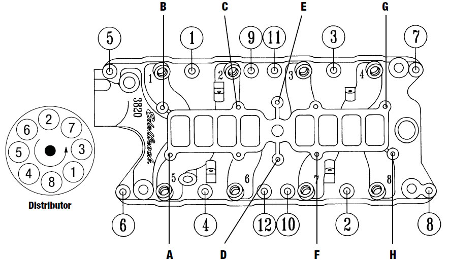
Effigy 1 - Intake Manifold Tightening Sequence, Manifold Elevation-To-Bottom Fastener Locations, and Firing Order Torque Bolts to eighteen-20 Ft./Lbs. 5.0L Ford Firing Order 1-3-seven-2-6-v-4-8 Turn Distributor Clockwise to Accelerate Timing
seven. Install upper manifold and gasket (dry) using hardware supplied (Come across Figure 1 and Fastener Location Chart Below). Upper manifold must be positioned and so that the throttle body is on the rider side of vehicle, not driver's side. Do not overtighten manifold base of operations-to-manifold upper fasteners. Employ a short box or open end wrench only.
NOTE: The 1-1/2" hex bolt in position "D" must be installed from the inside of the upper manifold plenum. Use liquid thread locking compound on this bolt to forestall accidental loosening and engine damage.
Fastener Location Chart
| LOCATION | FASTENER |
|---|---|
| A | 5/xvi" ten 1-3/8" Carb Stud |
| B | five/16" x 1-1/2" Carb Stud |
| C | 5/16" ten one-1/two" Carb Stud |
| D | v/16"-18 x 1-one/ii" Hex Head Bolt |
| E | Not Used |
| F | Non Used |
| 1000 | five/16" x one-1/2" Carb Stud |
| H | 5/16" 10 one-i/2" Carb Stud |
8. Install the plenum cover and gasket (dry) with the supplied Allen head bolts.
ix. Remove original throttle valve/EGR plate studs from stock manifold and install in new manifold. To re-install remaining components, opposite removal procedure. Adapt all command cables. If automatic transmission equipped using Edelbrock throttle body, refer to throttle trunk instructions for transmission T.V. (throttle valve) cable linkage aligning. Fill cooling organisation with coolant. Connect battery negative cable.
10. A re-torque of the manifold bolts is recommended after several operation cycles (start-up, bring to operating temperature, cooldown). Re-torque when engine is common cold.
FUEL LINE REMOVAL AND INSTALLATION
Circumspection: Practice not remove fuel lines unless necessary.
CAUTION: Fuel organization is under force per unit area. Pressure must exist released before servicing fuel system components.
1. Remove fuel cap to release fuel tank pressure. Using EFI pressure estimate (T80L-9974-B), release fuel pressure from fuel pressure level relief on fuel rail.
2. Before disconnecting fuel lines, disconnect negative battery cablevision. To disconnect fuel lines, remove retaining prune from outside of fuel line coupling.
3. Use Jump Lock Coupling Remover (D87L-9280-A) for iii/8" line or (9D87L-9280-B) for 1/2" line. Install jump lock coupling remover on fuel line then information technology enters cage opening (Meet Figure two).
four. Push spring lock coupling remover into cage opening to release female plumbing fixtures from garter bound. Pull couplings apart. Remove leap lock coupling remover.
5. To install fuel lines, install new O-rings on fuel lines. Apply only specified fuel resistant brownish O-rings. Earlier installing, lightly glaze O-rings with clean O-ring lube (brake lube). Clean fittings and replace garter leap, if necessary.
6. Fit female plumbing fixtures to male fitting and push until garter bound snaps over flared end of female person fitting. Ensure lines are locked together and garter spring is over female fitting flared end.
7. Install retaining clip. Ensure horseshoe portion of clip is over coupling. Practise non install retaining prune over rubber fuel line.
Note: Blackness retaining clip should be installed on fuel supply line and Greyness clip on fuel return line.
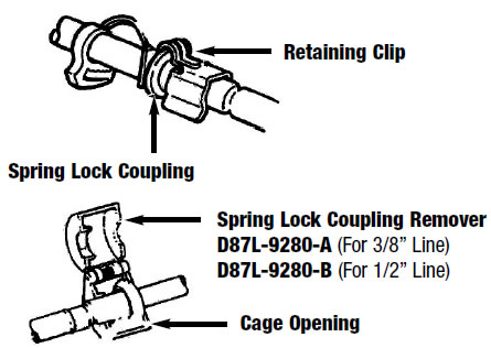
Figure 2 - Disconnecting Fuel Lines
All-time Sellers
Related Guides
-
Installation
-
Installation
-
Installation
Word on The Street
AmericanMuscle.com makes their shopping experience very easy by having the pick to only show parts that with fit with your specific model and sub-model of vehicle, making sure you lot you lot don't accidentally past incompatible parts.
FORD, FORD MUSTANG, MUSTANG GT, SVT COBRA, MACH 1 MUSTANG, SHELBY GT 500, COBRA R, BULLITT MUSTANG, SN95, S197, V6 MUSTANG, FOX BODY MUSTANG, AND v.0 MUSTANG ARE REGISTERED TRADEMARKS OF FORD MOTOR COMPANY. Contrivance, Contrivance CHALLENGER, DAYTONA 392, DAYTONA R/T, DODGE CHARGER, SRT 392, SRT8, R/T, RALLYE REDLINE, SCAT PACK, SRT HELLCAT, SRT DEMON, T/A, PENTASTAR, AND HEMI ARE REGISTERED TRADEMARKS OF FIAT CHRYSLER AUTOMOBILES (FCA). SALEEN IS A REGISTERED TRADEMARK OF SALEEN INCORPORATED. ROUSH IS A REGISTERED TRADEMARK OF ROUSH ENTERPRISES, INC. CHEVROLET, CHEVROLET CAMARO, CAMARO, LS, LT, LT1, SS, Z/28, ZL1, AND ECOTEC ARE REGISTERED TRADEMARKS OF Full general MOTORS LLC.. AMERICANMUSCLE HAS NO AFFILIATION WITH THE FORD MOTOR COMPANY, ROUSH ENTERPRISES, FIAT CHRYSLER AUTOMOBILES, SALEEN, OR GENERAL MOTORS LLC.. THROUGHOUT OUR WEBSITE AND PRODUCT CATALOG THESE TERMS ARE USED FOR IDENTIFICATION PURPOSES ONLY. 2003-2021 AMERICANMUSCLE.COM. ®ALL RIGHTS RESERVED
Source: https://www.americanmuscle.com/edelbrock-manifold-8695-install.html